Demystifying the basic lift equation
Many of us, when confronted with equations that we struggled with in the distant past, groan and turn the page. One of them that’s not that hard to deal with, and that’s highly useful for pilots to grasp, is how lift is created. Let’s take a look:
L= ½ CL * S * ρ * α * v^2
That’s not that ugly, let’s take a look at the basics of lift. In its simplest form, lift is a force created by the redirection of airflow as an airfoil passes through it. As a basic approximation, imagine a bunch of boxes of air that our hypothetical wing is flying through to see how it makes lift:
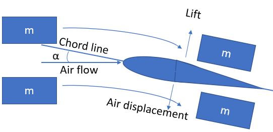
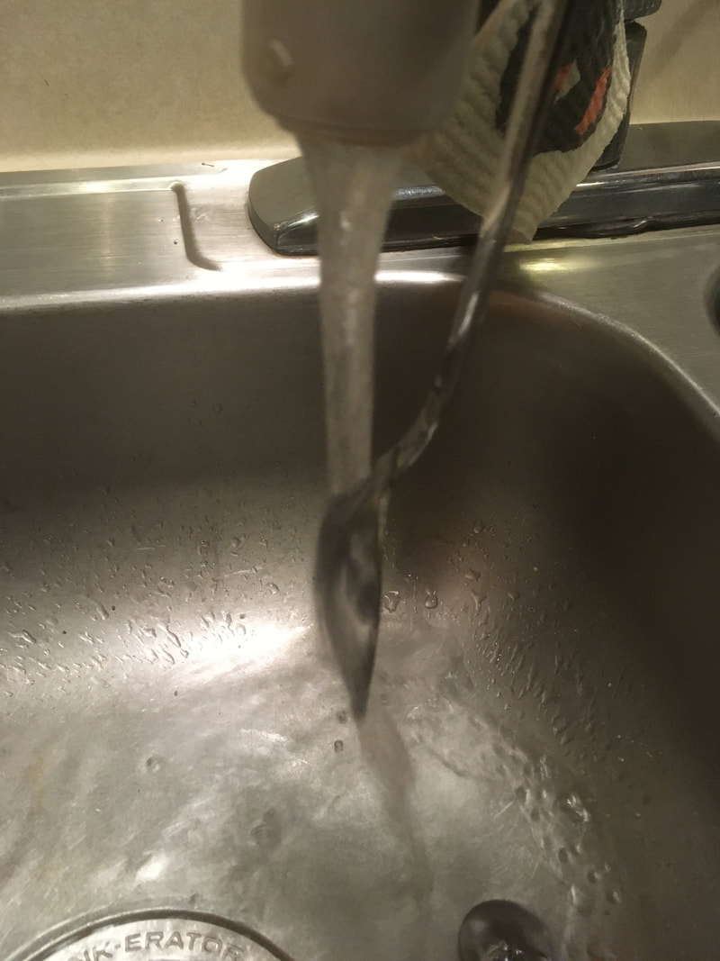
The boxes going over the top follow the contour, and the ones going underneath get pushed down. The net effect is that the boxes of air get pushed down by the wing. Applying Newton’s third law, the opposite reaction of this downward displacement of the air is lift exerted on the wing. A simple way to visualize this is to hold a spoon into a stream of water from a tap: the water arcs along the spoon, and the spoon gets pulled in the opposite direction. Mentally spin that horizontal, and you've got a wing.

Now that we’ve got the basic idea, let’s look at what each piece of the lift equation means:
½ is a coefficient that makes the units work, so not much else to worry about there.
CL is the coefficient of lift, which is a property of the airfoil. As you change camber and other attributes, the amount of lift the shape produces will change. Designers try to maximize the CL while minimizing CD, and often design in an ability to change the shape of the wing (e.g. flaps, slats) for different flight regimes.
S is the area of the wing. As we increase the area, we redirect more molecules, so we’d expect the lift to scale linearly with area.
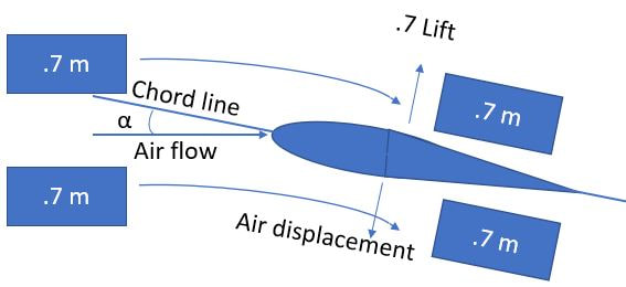
ρ (the Greek letter “rho”) is the density of the air, normally 1.225 kg/m^3 at sea level ISA (ρ0, or “rho-naught, the default value). The amount of lift created when our wing passes through a given volume will depend on the mass of that air, so as that mass changes, it’s reasonable to expect the lift to scale linearly provided we don’t mess with anything else. In our image, if all the boxes weigh .7m, then ceteris paribus we’ll get .7 lift.
½ is a coefficient that makes the units work, so not much else to worry about there.
CL is the coefficient of lift, which is a property of the airfoil. As you change camber and other attributes, the amount of lift the shape produces will change. Designers try to maximize the CL while minimizing CD, and often design in an ability to change the shape of the wing (e.g. flaps, slats) for different flight regimes.
S is the area of the wing. As we increase the area, we redirect more molecules, so we’d expect the lift to scale linearly with area.
ρ (the Greek letter “rho”) is the density of the air, normally 1.225 kg/m^3 at sea level ISA (ρ0, or “rho-naught, the default value). The amount of lift created when our wing passes through a given volume will depend on the mass of that air, so as that mass changes, it’s reasonable to expect the lift to scale linearly provided we don’t mess with anything else. In our image, if all the boxes weigh .7m, then ceteris paribus we’ll get .7 lift.
This is why I find it easier to think of density in terms of σ (sigma), the ratio of actual density, ρ, to ISA SL, or σ=ρ/ρ0. “Density altitude” is just an abstraction that makes life difficult. If you tell me σ=.9 today, then I can guesstimate the effect on my airplane’s performance. If you tell me my plane will behave as it would at 3400’ ISA, then that’s a bit harder to work with, but YMMV.
α (the Greek letter “alpha”) is our angle of attack, the angle at which our wing meets the oncoming air. As we increase this angle, the angular deflection of the air increases proportionately, and hence so does the vertical deceleration. Thus 2α -> 2 lift, at least as long as the airflow stays attached, which it does until the critical angle where flow separation occurs, beyond which we start losing lift.
α (the Greek letter “alpha”) is our angle of attack, the angle at which our wing meets the oncoming air. As we increase this angle, the angular deflection of the air increases proportionately, and hence so does the vertical deceleration. Thus 2α -> 2 lift, at least as long as the airflow stays attached, which it does until the critical angle where flow separation occurs, beyond which we start losing lift.
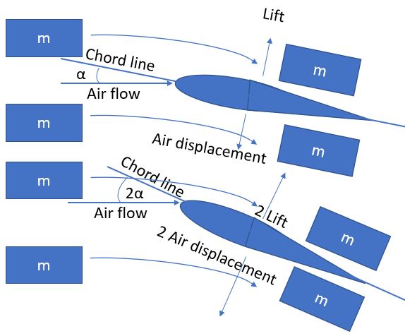
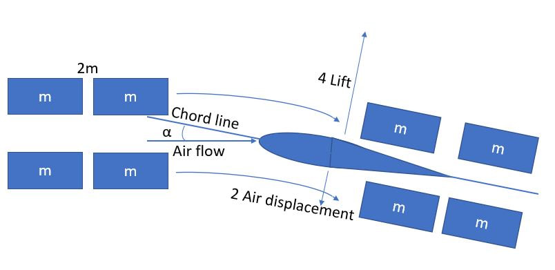
v^2 is a trickier one. We intuitively expect lift to increase as speed does, but quadratically? Imagine a wing moving through an airmass with all other variables held constant, and then let’s double the speed and see what happens. In a given time frame, we’re passing through, and hence redirecting twice the volume (and hence mass, 2m). We’re still redirecting it with the same angular change, meaning that it’s getting redirected down with twice the acceleration. Thus, we end up with 2m and 2x displacement, for a total 4x increase in downforce, and consequently lift. Plugging it into Newton’s Second Law (F=ma) checks as well: 2m * 2a = 4F. Thus, lift scales as the square of TAS, ceteris paribus.
Ok, that wasn’t so bad, was it? (Quick, let me disable the comments function, I’ll be right back…). Following up, there will be a few more articles on how we can apply this to be better pilots.